 Русский


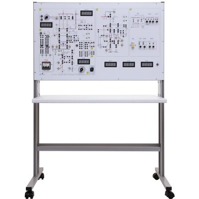
Relay protection and automation
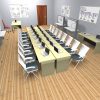
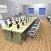
The training laboratory “Relay protection and automation” is designed for secondary specialized and higher educational institutions.
3D-model
Laboratory quantity
 |
NTC-09.02 “Means of automation” The laboratory unit is intended for the development and implementation of the circuits of automatic control based on PLC. More details >> |
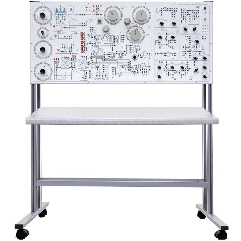 |
NTC-09.12 “Basic automation and computer engineering” The training laboratory equipment provides opportunity for studying parameters of individual elements of automatic equipment and follow-up systems based on self-synchronous devices and potentiometers as well. More details >>
|
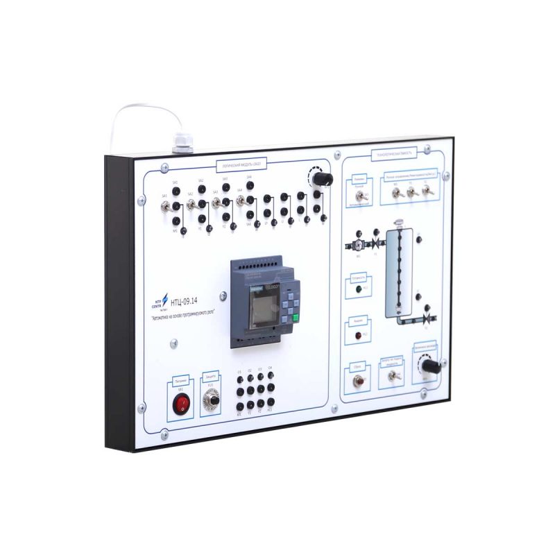 |
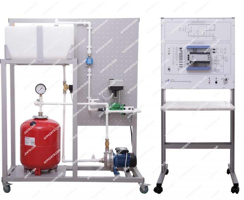
NTC-09.14 “Automation on the basis of programmable relay” Training laboratory bench is designed to study the programmable relay and the options for its industrial applications in the construction of automated control systems. The controled object is a model of technological reservoir. More details >>
|
 |
NTC-09.22 “Smart Home” Laboratory experiments for training specialists in automation of premises are conducted using the bench. The principal element base and performance characteristics of separate systems of control as well as techniques of event process programming are studied. More details >> |
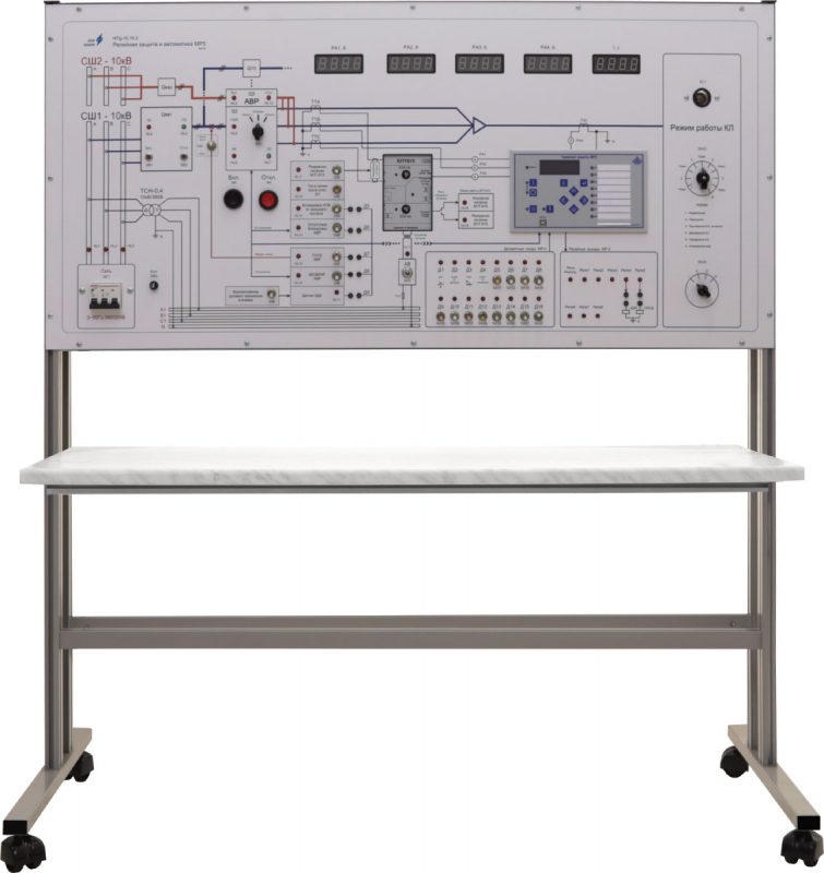 |
NTC-10.10.3 “Relay protection and automation МR5” The stand allows conducting the following operations:
More details >> |
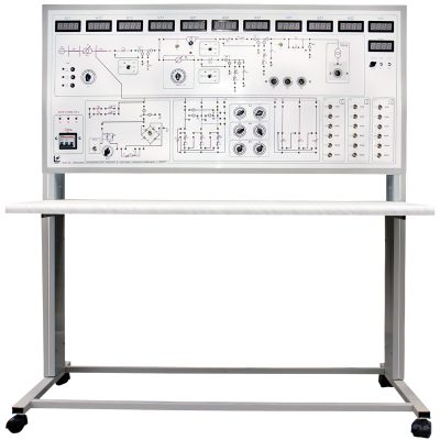 |
NTC-10.65 “Quality of electric energy in power supply systems with MPMS” The training laboratory equipment allows to study the electric transmission line model under active-inductive load with opportunity to connect the balancing capacitors. More details >> |
 |
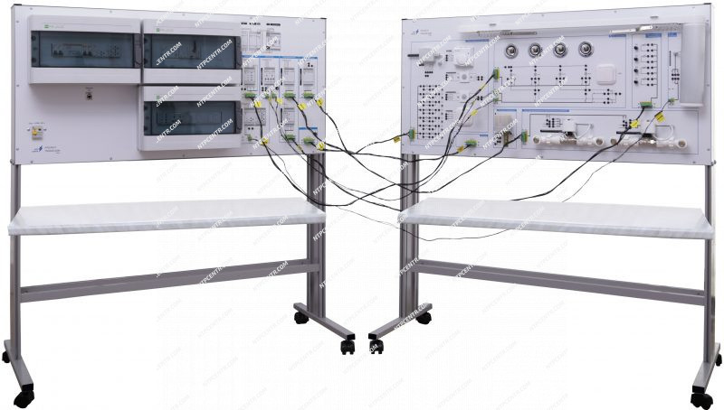
NTC-10.66 “Relay protection and automation in power supply systems with MPMS” The laboratory training equipment allows to study the relay protection units and automation of power supply systems. More details >> |