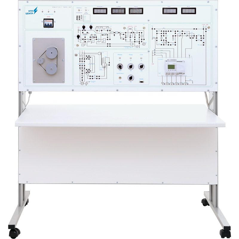
Has two h/w versions: full size bench top version and table version.
The following equipment is located inside:
- power unit +5 V (current 1 А), +15 V (current 1 А), -15 V (current 1 А), +18 V (current 0,1 А), +110 V (current 1 А), +24 V (current 2 А);
- control unit and thyristor voltage regulator circuit board;
- rectifiers circuit board;
- relay unit;
- autotransformer.
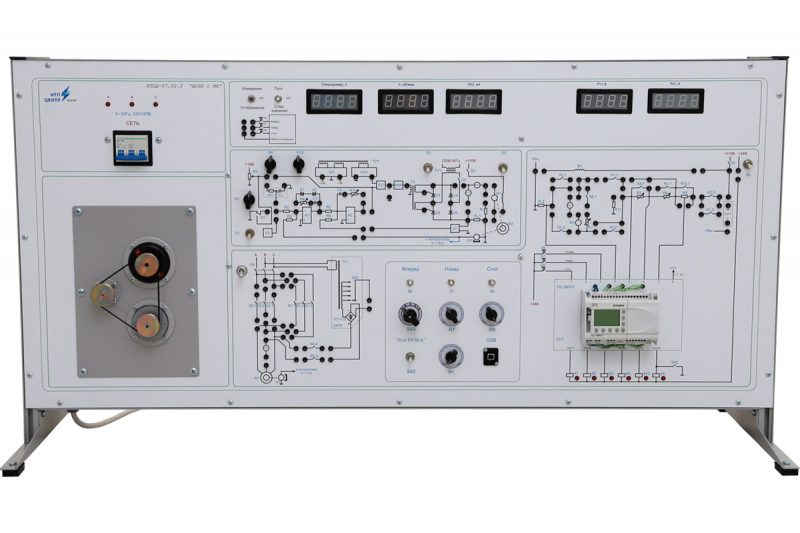
The front panel has electrical schematics of investigated objects. All scheme, displayed on the panel, are divided into groups according to the theme of conducted experiments. The panel includes: switch sockets, four digital equipment (voltmeter, ammeter, speed meter), DC motor, AC motor, tachogenerator, alpha-controller – further PLC, switch gear apparatus, controls, allowing to change elements parameters during laboratory experiments.
Functionally, the front panel is divided on six units:
- Control schematics of DC electric motor. The unit allows to investigate DC motor start in time function, in reactance voltage function, in current function, braking in time function, in reactance function, plugging, using PLC.
- Control schematics of asynchronous electric motor. The unit allows to investigate the start, reverse, plugging, dynamic braking of asynchronous motor with squirrel-cage rotor, using PLC.
- Thyristor converter and closed control system DCM unit. Thyristor regulator provides smooth measurement of output voltage from 0 to 80 V. Closed control system has back current and speed couplings.
- Electric machine unit with following installed equipment: DC electric motor, asynchronous motor with squirrel-cage rotor and tachogenerator. The electric cars shafts are connected mechanically.
- Regulators unit. Regulated switch resistors in motor armature circuit, dynamic braking current regulators, RS-485 socket to connect to PC.
- Equipment and power supply unit. Power switch, LED switch power indication in each phase are located inside the unit. Digital indicators measure direct and alternating current and voltage, frequency and rotation direction.
To conduct laboratory experiment it’secessary to assemble the circuit of investigated object, using jumpers, which allow to show the circuit in visual form.
The control system basis is alpha-controller, allowing flexibly change operation algorithm of executive relays, using different logical functions, counting functions, time delay, analogue and discrete signals analysis.
PLC operating algorithm flowcharts are created on PC, using special program, included in the set. Then the flowchart is saved to the PLC memory. The set includes turnkey solutions (flowcharts) to conduct the laboratory experiments.
The training system is supplied with:
- a software to test and pass students before the experiment. Both theoretical knowledge and knowledge of the contents of the laboratory experiment are checked. As a result of testing the student receives the mark;
- a software of digital measurement equipment (during laboratory works gives opportunity for saving 50 samples of obtained data with discreetness of 0,2 for plotting the transient processes curves);
- a software of alpha-controller;
- a set of teaching materials and technical documentation intended for the teaching staff.