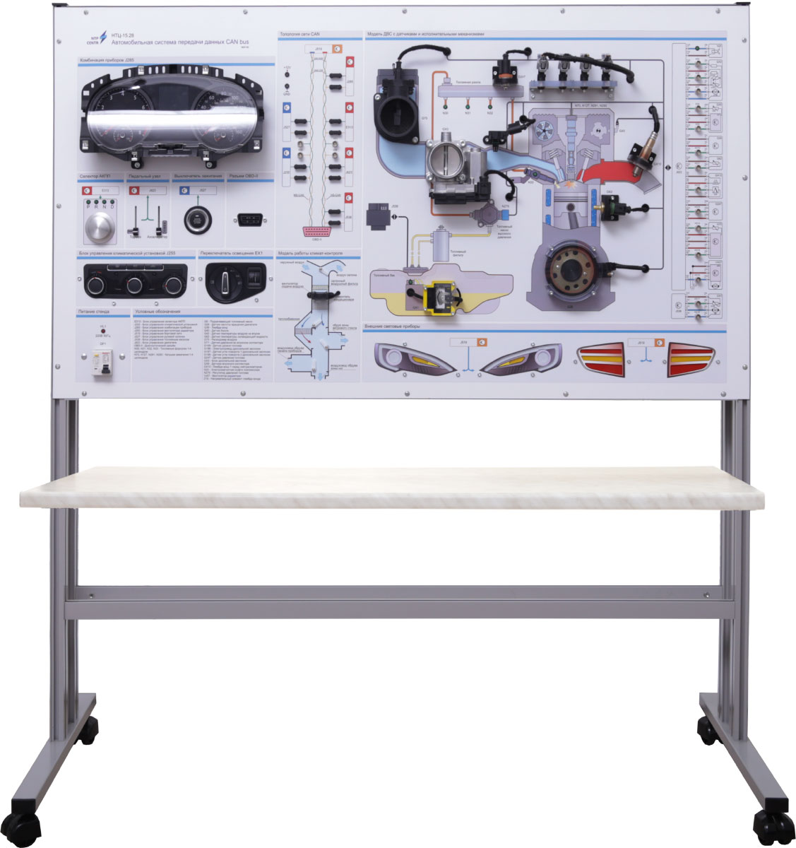
The stand is a sinlge-standing unit and internally contains:
- Electronic modules.
- Power supply unit.
- Residual current protective devices (RCDs).
- Control and visualization elements.
- Worktop surface.
A graphical functional diagram is displayed on the front panel, illustrating the operation of internal combustion engine (ICE) control systems, with explanatory labels and indications of interconnections between components.
The stand also includes simulated components that mimic the operation of real devices interacting over the CAN bus:
- ICE sensors, such as:
- Crankshaft position sensor.
- Mass airflow sensor.
- Intake manifold pressure sensor.
- Throttle position sensor.
- Engine coolant temperature sensor.
- Oxygen sensor.
- Fuel level sensor.
- Actuators, including:
- Fuel injectors.
- Throttle valve.
- Cabin fan.
- Fuel pump.
- External lighting equipment.
- Electronic Control Units (ECUs) for:
-
- Engine.
- Lighting system.
- Climate control system.
- Fuel pump.
- Gear selector.
- Instrument cluster.
- Steering column (Start/Stop switch).
- OBD diagnostic connector.
- BNC connectors for oscilloscope connection, CAN bus signal analysis, and sensor signal monitoring.
The stand provides extensive opportunities for both theoretical and practical training in the following areas:
- Principles of design and operation of automotive CAN networks.
- Interaction between sensors, actuators, and ECUs.
- CAN traffic analysis: sniffing and decoding.
- Error handling at the protocol and physical levels.
- Study of the UDS (Unified Diagnostic Services) protocol.
- Working with diagnostic equipment via the OBD connector.
The stand has the following interactive features:
- Engine Start Simulation: When the Start/Stop button is activated via the steering column ECU, the bench simulates engine operation. The injectors are activated, crankshaft sensor pulses are generated, and the throttle valve is engaged.
- Instrument Cluster Response: The instrument cluster receives real-time CAN data and displays relevant parameters such as engine speed, gear position, temperature, and status indicators.
- Climate Control Simulation: The bench is equipped with a fully functional climate control unit modelling standard automotive equipment. Adjustments to temperature or airflow direction via physical controls are transmitted over the CAN bus.
The graphical panel visualizes:
- Flap movement.
- Fan operation.
- System response to user input.
This allows students to observe not only the logical, but also the visual behavior of the climate system in a full simulation mode.
The diagram on the front panel illustrates:
- Placement of sensors and actuators within the ICE system.
- Engine control system structure.
- CAN network topology between ECUs.
- Climate control system model, showing flap and fan status.
The laboratory stand comes with:
- A set of teaching and technical documentation intended for the teaching staff.
- Software.