NTC-16.44 “Means of automation and control in water supply systems”
Br0.00
The training laboratory unit is designed to be used as a teaching facility for secondary and higher educational institutions.
- Description
- 3D model
- Experiments provided
- Technical specifications
- Scope of delivery
- Additional equipment
- simulate automation systems of technological equipment;
- study automation hardware, drive systems and control systems irrespective of industry affiliation;
- gain skills on technological equipment adjustment;
- study the functioning and programming of discrete and analog automatic control equipment.
The training systems consists of two parts:
- laboratory training unit;
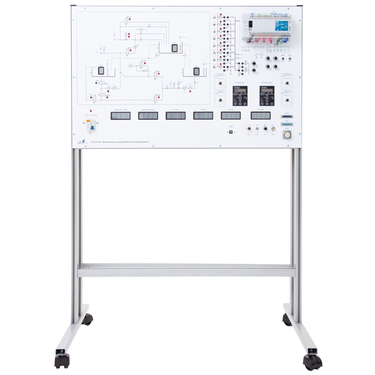
- control unit.
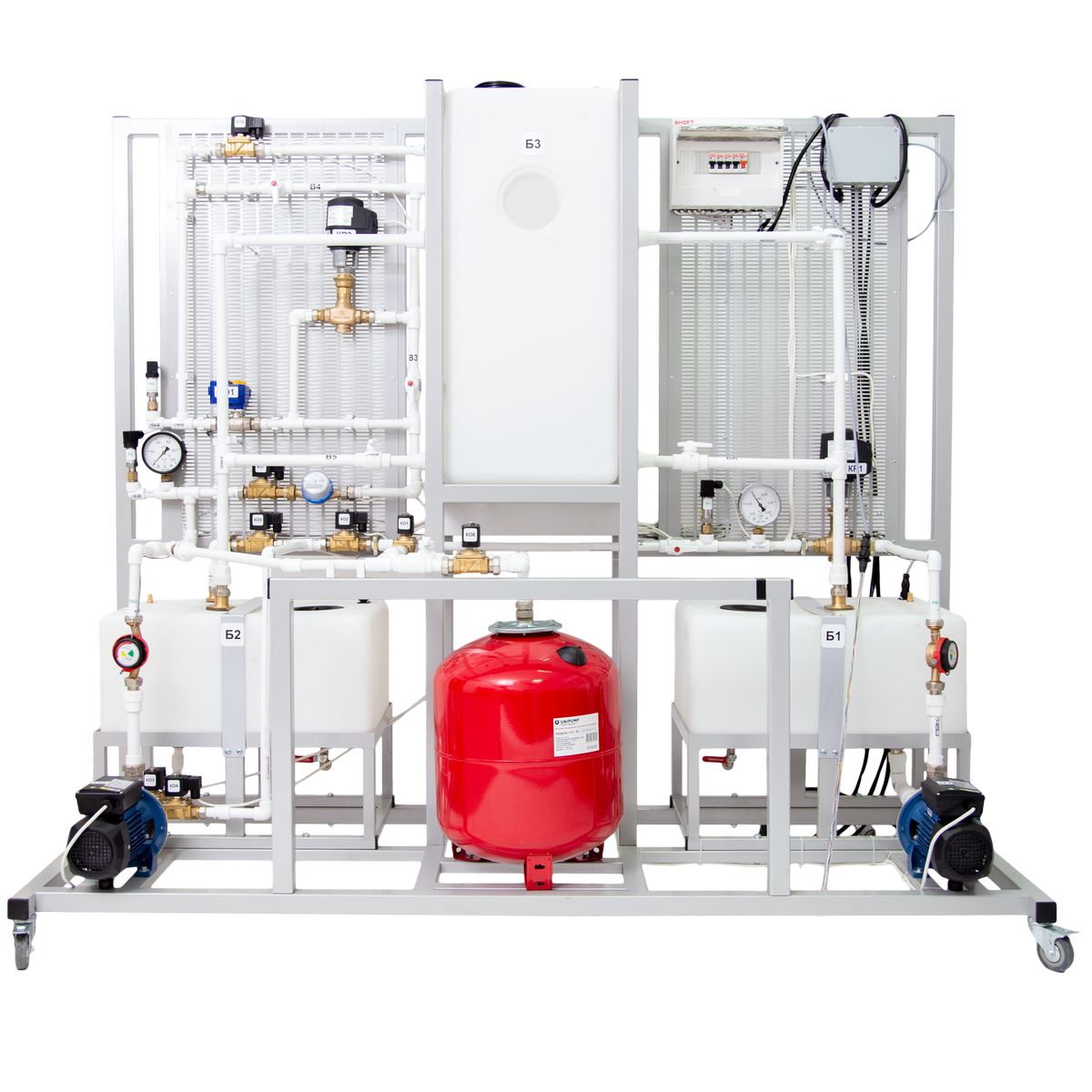
In the laboratory training unit, a physical model of 3 communicating vessels with a changeable configuration of the connection is used as the control object.
The laboratory training unit is a floor structure in the form of a frame rack with the following equipment installed:
- physical model of communicating vessels;
- pumps – 2 pcs.;
- control valve with position sensor – 2 pcs.;
- pressure sensor – 3 pcs.;
- level sensor – 3 pcs.;
- flow sensor – 2 pcs.;
- cut-off valve – 8 pcs.;
- electric butterfly valve – 1 pc.;
- pressure gauges – 2 pcs;
- hydraulic accumulator – 1 pc.
The front panel of the control unit includes: a microcontroller, controls, switching sockets, “Power” indicator and local panels of inverter operators. For convenience, there’s a schematic hydraulic diagram and a connection diagram of the inputs and outputs of the microcontroller printed on the panel.
The control unit includes: power supply boards, level sensors and rectifiers; electromagnetic relays; power transformer and transformers of electromagnetic valves; inverters. The power transformer provides the necessary voltage to power the training system.
The training system is supplied with a set of methodological and technical documentation intended for the teaching staff.
3D model
Experiments provided
- Studying the principle of operation and technical characteristics of pressure, flow and level sensors.
- Studying the principle of operation and technical characteristics of actuators: electric valves, control and shut-off valves.
- Studying the technical characteristics and programming of the parameters of electromechanical system: asynchronous motor, pump, frequency converter.
- Studying the control unit of the automation system; architecture of a distributed automation system; automation system software; SCADA system software.
- Studying a closed flow rate maintenance system: setting the flow rate in the investigated system.
- Studying a closed flow control system when changing the control law.
- Studying a closed pressure maintenance system.
- Studying a closed pressure control system when changing the control law.
- Determination of pressure characteristics of the pump during the independent operation of each pump on its own pipeline.
- Studying the characteristics of pipelines with local resistances in the form of valves.
- Studying the characteristics of the series-connected pumps.
- Studying the characteristics of parallel-connected pumps.
- Pipeline ramp up with simultaneous start-up of pumps.
- Pipeline ramp up with simultaneous start-up of electric motors with automatic control for each of them, using a frequency controller.
- Ensuring a given performance with given pressure limitations at specific points of the pipeline.
- Studying the principle of operation and technical characteristics of the sensors of executive devices in automation system: pressure, flow and level sensors, control and shut-off valves.
Technical specifications
| Power supply | ~50 Hz, 220 V (single-phase 220 V, 50 Hz) | |
| Power consumption, W, max | 800 | |
| Controlled object overall dimensions, max | ||
| width, mm | 2000 | |
| height, mm | 1800 | |
| depth, mm | 800 | |
| Control unit overall dimensions, max | ||
| width, mm | 1020 | |
| height, mm | 1450 | |
| depth, mm | 600 | |
| Controlled object weight (without water), kg, max | 100 | |
| Control unit weight, kg, max | 50 | |
Scope of delivery
- training laboratory equipmеnt – 1 pc.;
- jumpers set – 1 pc.;
- passport – 1 pc.;
- accompanying materials in electronic format – 1 pc.
 Русский


