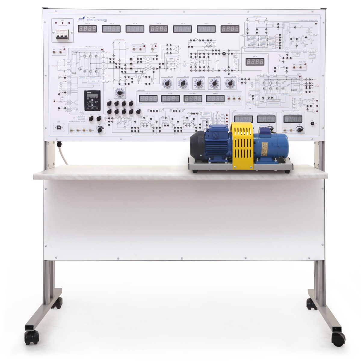
- a housing where are mounted electric equipment, electronic cards, the front panel;
- an electric machine unit containing two electric machines: an asynchronous electric motor with a squirrel-cage rotor and a DC electric motor with independent excitation. The machine unit is equipped with an optical speed sensor.
The stand body contains:
- Frequency converter designed to form a three-phase alternating current network of adjustable frequency and supply voltage of an asynchronous electric motor. The frequency converter gives opportunity to study an asynchronous motor in all four quadrants of the mechanical characteristic, as well as to implement dynamic braking of a motor with adjustable current.
- Two pulse-width converters designed to power the armature circuit, the excitation winding of a DC motor or an active-inductive load. Pulse-width converters are implemented on the element base of the frequency converter. Two of its arms are used to obtain a reversible PWM, and the remaining arm is used as a non-reversible PWM to power the DC excitation winding. The reverse PWM can operate in symmetrical (alternate diagonal connection) or asymmetric (diagonal connection of one pair of transistors) mode.
- Three-phase controlled rectifier designed to study the work on active, inductive and motor loads. The rectifier is based on the microcontroller and power thyristors. The controlled rectifier has two modes of operation: three-phase controlled by a microcontroller and single-phase with an analog system of pulse-phase regulation.
- Measurement module built on the basis of digital measuring instruments and designed to measure and display the current in the excitation winding of a DC motor, as well as measure voltage and current between pulse-width converters and a frequency converter.
- Relay-contactor control, which provides opportunity to perform:
- rheostatic start of a DC motor in three steps as a function of: current, EMF, speed or time;
- dynamic braking of a DC motor as a function of: current, emf, speed or time;
- DC motor braking by anti-switching;
- induction motor dynamic braking and reverse current braking.
Microprocessor control of the relay-contactor control unit allows to:
- measure the current, voltage and speed of the DCM and memorize them at 0.1 second intervals for 10 seconds after the start/deceleration start. This serves for plotting the start/deceleration curves without using a PC;
- give output analog signals proportional to current and speed DCM; studying a servo drive system based on a DC motor. The speed measurement is based on the signals of the pulse encoder.
- Analog controllers designed for the study of closed systems:
- single-loop current stabilization DC motor;
- single-loop speed stabilization DC motor with speed controller;
- single-loop voltage stabilization DC motor with speed controller;
- double-circuit voltage stabilization of the DC motor with voltage and current regulators;
- double-circuit stabilization of the speed of the DC motor with speed and current controllers.
- Resistors in the armature circuit (three stages).
- DC Motor Dynamic Brake Resistor and Reverse Current Resistor.
- Power starters of the relay subsystem.
- Overvoltage energy reset resistors at smart modules.
The front panel shows the electrical circuits of the objects under study. All circuits shown on the panel are divided into groups according to the subject of the work being done. The panel is equipped with switching jacks, indicators of digital devices, switching equipment, as well as controls that allow you to change the parameters of the elements during laboratory work. Also, the control points of input, intermediate and output signals of power converter equipment are displayed on the front panel.
Controls on the front panel of the stand:
- reference potentiometer for control of a reversible pulse-width converter, toggle switch for the converter operation mode (independent / symmetrical);
- setting potentiometer of a pulse-width converter for powering the excitation winding of a DC motor;
- setting potentiometers of the frequency converter, allowing smoothly changing the output frequency setting, output voltage, dynamic braking current of an asynchronous electric motor with a phase rotor;
- setting signal potentiometers for setting a closed system, adjusting the feedback coefficients for current and speed;
- thyristor regulator opening angle setting potentiometer, regulator operation mode toggle switch (three-phase digital/single-phase analog);
- controls of stopwatch and of three-stages starting;
- relay subsystem controls.
For doing the experiment, it is necessary to connect the circuit of the object under study using unified jumpers that allow you to connect circuits without losing their clarity.
The stand is accompanied with a set of teaching materials and technical documentation intended for the teaching staff.