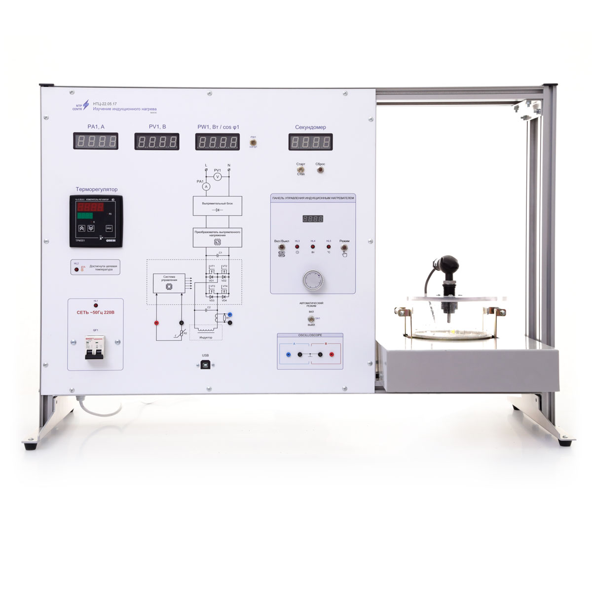
The control unit consists of a housing made of aluminum profile, in which the following electrical equipment is installed:
- power supply unit +12V;
- induction heater;
- communication board with PC;
- measuring instrument-regulator;
- stopwatch;
- oscilloscope;
- electrical energy meter.
At the front panel mounted into the housing are placed the following elements:
- electrical functional circuit for connecting an induction heater;
- control panel of the meter-regulator;
- controls for the induction heater;
- digital indicators of the electrical energy meter;
- sockets for measuring actual electrical signals;
- USB connector;
- protection organs (circuit breaker).
The front panel of the control unit is functionally divided into two parts. On the left side there is an induction heater control panel, measuring instruments, a functional diagram of the heater, oscilloscope leads and test sockets.
Using the control panel of the induction heater, you can set the required heating power and temperature, as well as set the heater’s operating time.
You can control the time it takes to reach a certain temperature using a stopwatch operating in manual or automatic mode.
The meter-regulator is used to measure the temperature inside the container using a temperature sensor. The temperature sensor has the ability to adjust the height of the measuring head.
The electrical energy meter allows to measure voltage, current, power, as well as cos φ in the primary power circuit of an induction heater.
The built-in oscilloscope is designed to measure and visually study the actual signals on the inductor and the built-in heater temperature sensor. To use the oscilloscope, you need to install special software on your PC.
An induction heater is located on the right side of the front panel. The heater is located inside the metal case, which increases the mechanical strength of the product.
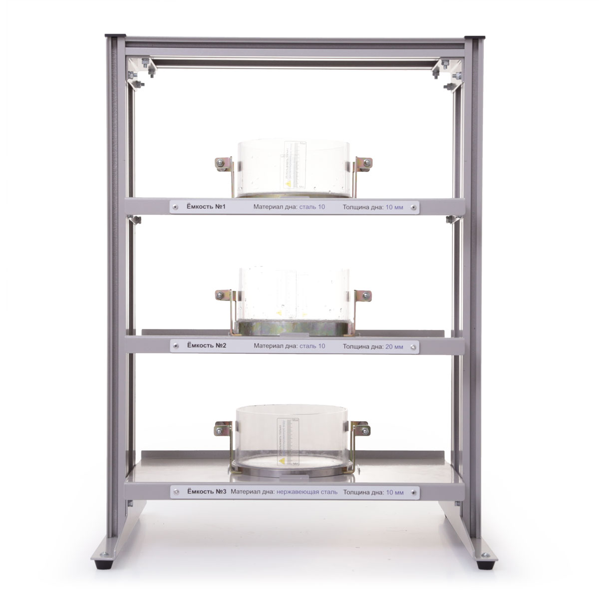
Container for experiments has:
- bottom part made of metal suitable for induction plates. The bottom part are made a groove for mounting the wall, as well as recesses for attaching the handles. Containers of different bottom thicknesses are supplied with the stand;
- walls made of transparent polycarbonate pipe. Transparent walls give opportunities to observe cavitation processes during the heating of the container;
- metal handles for safety reason are protected with plugs from fluoroplastic.
The stand is accompanied with:
- a set of teaching materials and technical documentation intended for the teaching staff;
- software.