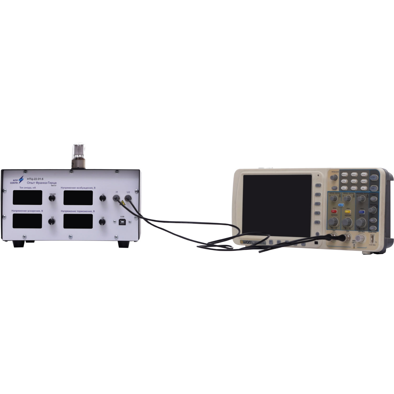
The stand is designed as a desktop panel device.
The housing includes front and rear panels.
On the front panel of the stand, the following components are installed:
- Schematic diagram illustration.
- Controls for adjusting the retarding voltage.
- Controls for adjusting the accelerating voltage.
- Control for adjusting the degree of cathode heating.
- Measurement system indicators.
The rear side of the stand contains electrical protection circuitry, switches for turning on/off the measuring devices, a USB port, and sockets for connecting oscilloscope probes.
Inside the stand there is a power supply unit, a measurement system, and a board for computer communication. The measurement system is intended for measuring and displaying the investigated parameters (current, voltage).
The laboratory stand comes with software and teaching materials.