NTC-11.94 “Hydraulic equipment with electric proportional control”
Br0.00
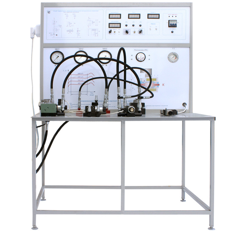
The stand is designed for experimental investigation of: proportional electromagnet; discharge hydraulic valve, hydraulic distributor, reducing valve and three-port flow regulator with proportional control.
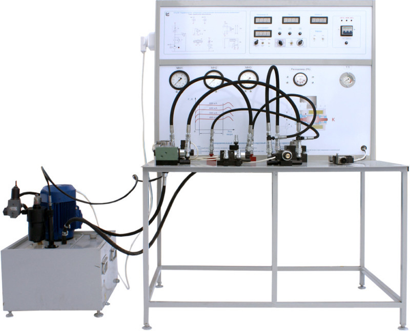
The hydraulic station consists of a hydraulic tank, a gear pump, driven into rotation from an asynchronous three-phase electric motor. A filter and a pressure hydraulic valve are installed in the pressure line of the pump.
The stand has a frame structure with a table and two panels: hydraulic and electric. A two-line flow regulator and research objects – four devices with electric proportional control (pressure valve, hydraulic valve, pressure reducing valve and three-line flow regulator) are installed on the table. In addition to the listed units, on the table is installed a proportional magnet, which is also experimentally under study.
On the hydraulic panel are installed:
- adjustable throttle;
- flow meter;
- thermometer;
- three manometers;
- two sockets for connection to manometers.
The stand has a non-rigid (variable) structure. Structuring the scheme is carried out using elastic pipelines with quick disconnect connections (BRS). Each BRS consists of two parts: half couplings with a check valve and half couplings with a lock. The stand includes a set of flexible pipelines. Half-couplings with clamps are installed at the ends of the pipelines. Two pipelines are simple, that is, they do not have branches, and the remaining two have branches (of smaller diameter). Branches are used to connect to a pressure gauge.
On the electrical panel of the stand, a hydraulic circuit diagram of the stand is shown, as well as electrical control devices for the stand and its subsystems and digital registration of parameters.
To register the time passing through the flowmeter of a given volume of liquid (for subsequent determination of flow), an electronic stopwatch is installed on the stand.
The training system is supplied with technical and methodical documentation for teaching staff.
Experiments provided
- Investigation of proportional electromagnet characteristics.
- Study of construction and determination of characteristics of discharge hydraulic valve with proportional control.
- Study of construction and determination of characteristics of hydraulic distributor with electric proportional control.
- Study of construction and determination of characteristics of reducing valve with proportional control.
- Study of construction and determination of characteristics of three-port flow regulator with proportional control.
Technical specifications
| Power supply | 3~50 Hz 380 V 3P+PE+N | |
| Power consumption, kW, max | 3 | |
| Rated pressure in hydraulic system, MPa | 5,0…5,2 | |
| Hydro tank volume, dm3 | 30…35 | |
| Recommended working fluids | mineral oils MGE-46В, MG-30u, М-8V | |
| Overall dimensions, max | ||
| width, mm | 1200 | |
| height, mm | 1800 | |
| depth, mm | 900 | |
| Hydro station overall dimensions, max: | ||
| width, mm | 500 | |
| height, mm | 550 | |
| depth, mm | 700 | |
| Weight, kg, max | 80 | |
| Hydrostation weight (oil-free), kg, max | 40 | |
Scope of delivery
- training system – 1 pc.;
- hydro station – 1 pc.;
- accompanying materials in electronic format – 1 pc.;
- passport – 1 pc.
 Русский


