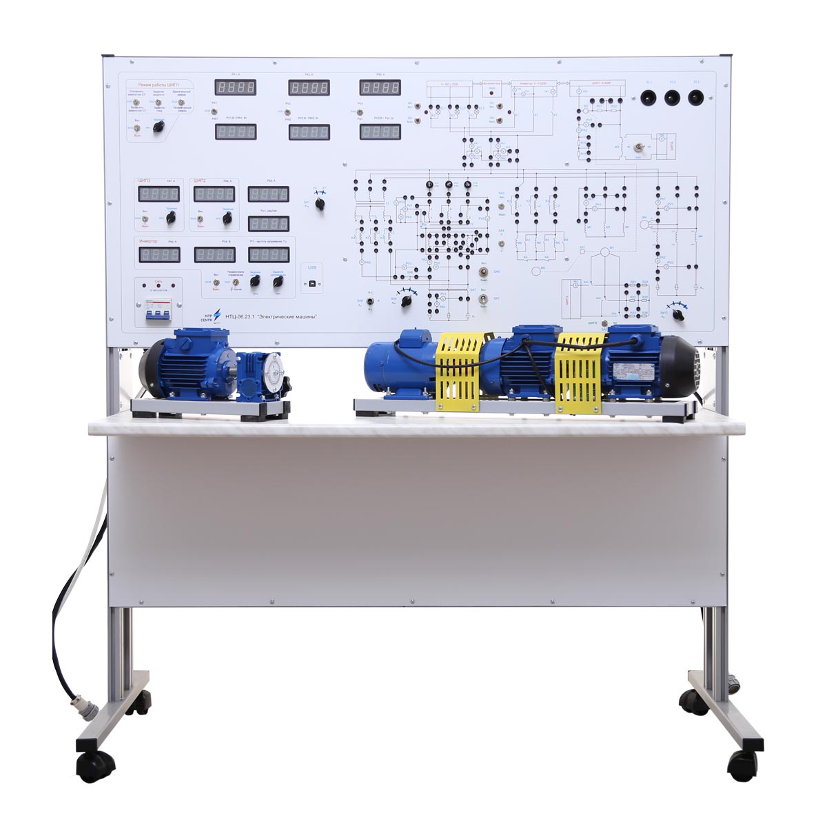
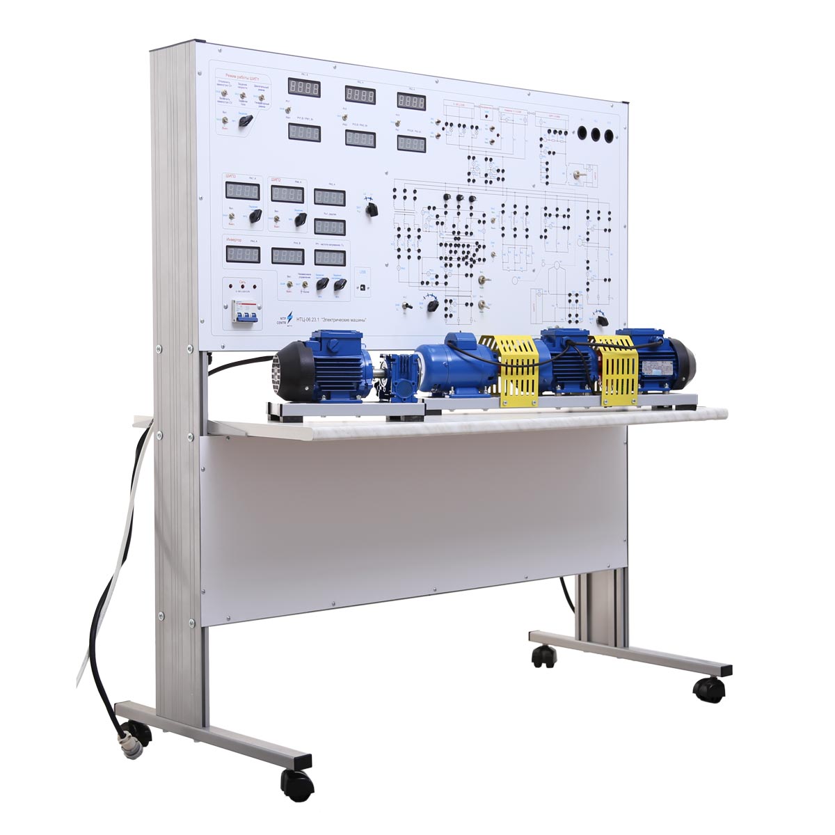
NTC-06.23.1 “Electrical machines with MCS”
Br0.00
The training laboratory system is designed to be used as educational equipment during laboratory works under the course “Electrical machines” in universities and specialized schools.
- case with installed part of electrical equipment, electronic boards, front panel and countertop integrated desktop;
- electronic unit №1, which consists of one DC motor of independent excitation,one asynchronous electric motor with squirrel-cage rotor, one asynchronous electric motor with phase rotor, pulse speed sensor, determining the direction of rotation;
- electronic unit № 2, which consists of induction regulator with worm reduction gearbox. Shaft rotation is carried out via the handle through the gearbox. The angle of rotation of the shaft regulator is displayed on the scale between -180° to + 180°.
The training system is complected by the electric machine units, based on the low power electric motors (90 W).
The case of the training system includes:
- Frequency converter, which is used to form three-phase circuit of AC adjustable frequency and voltage. The converter is made on the base of microcontroller and smart power module. The controller is used to input counts (voltage and frequent settings) and output signals (current, voltage), to organize data exchange with the PC, to export measured values on the front panel of the training system. The power module consists of the power circuits of three-phase rectifier bridge, three-phase IGBT bridge inverter, the drivers’ circuits and the protection against short-circuit voltage, low driver power supply, incorrect control signals. The frequency converter allows to investigate asynchronous motor in all four quadrants of the mechanical characteristic.
- Three pulse width converters, which are used for power supply of anchor circuit and DC motor excitation windings, and for power supply of the rotor circuit of asynchronous motor with phase rotor in the mode of synchronous motor and generator. Two pulse width converters are located on the element base of the frequency converter. Its two arms are used to get reversible PWC, another arm is used as non-reversible PWC for power supply of phase-wound rotor induction motor in the mode of synchronous motor. The power supply of excitation winding is realized on the separate MOSFET transistor.
The control system is designed on the base of microcontroller. It realizes input counts (voltage, frequency and dynamic braking current settings) and output signals (armature, frequency and rotor current), organization of data exchange with PC, export measurement values on the front panel of the training system. Pulse width converter of the DC motor anchor circuits is added by the operating mode of the closed system (current or speed regulation), and generator operating mode.
- The measurement module is designed on the base of digital measurement equipment. Instead of current and voltage measurement, each channel can count:
- existing value of alternating current and voltage;
- phases shearing angle between current and voltage;
- active power.
The measured values can be displayed on the front panel of the training system or to be transferred to the computer.
- Relay contactor control, which allows:
- Switch connection scheme of asynchronous electrical motor with squirrel-cage rotor.
- Input inductances in the stator’s circuit of the asynchronous electrical motor with squirrel-cage rotor, in the circuit of parallel (second) three-phase transformator.
- Measure load resistance value in three-phase circuit.
- Connect asynchronous electric motors to the mains or frequency converter.
- Resistors in the excitation winding circuit (two levels).
- Load resistors in three-phase circuit (four levels).
- Overvoltage energy drop resistors on the smart modules.
- Incandescent lamps for three-phase generator synchronization with network.
- Double winding transformers.
Frequency and pulse width converters are switched on intra-network collaboration (recuperation mode) to reduce power consumption from the network.
The electrical schemes of investigated objects are located on the front panel. The schemes, located on the panel, are split into groups, according to the theme of works. On the panel of the training system the following equipment is installed: switch sockets, indicators of digital units, switch gear apparatus and control units, allowing to change elements’ parameters during the laboratory works.
Control elements on the front panel of the training system:
- setting potentiometer to conduct a pulse width reversible converter;
- setting potentiometers of pulse width converters for power supply of DC motor excitation windings and the rotor of electric motor with phase rotor;
- setting potentiometers of frequency converter to allow smoothly change an imput frequency (0 ÷ 163 Hz), output voltage (0 ÷ 220 V);
- control elements of relay subsystem.
To carry out laboratory works, It’s necessary to collect the scheme of investigation object, using unified jumpers, which allow to show the scheme in visual form
It’s possible to carry out the laboratory works both in a manual mode, and in dialogue mode with PC.
The training system is supplied with:
- a set of teaching materials and technical documentation intended for the teaching staff;
- software provides the following opportunities:
- studying theoretical materials;
- perform an initial test and consolidate the acquired knowledge using the test included in the software;
- perform the experiment in the dialogue mode with PC according to the detailed instructions, registering your observations and measurements in the appropriate fields and tables of the program. Based on the obtained data, the program provides implementation of calculations and the construction of curves (depending on the content of the laboratory work);
- generate a final report about laboratory work, saved in .doc format.
Experiments provided
- Study of two winding power transformer.
Investigation of single-phase transformer in various modes, the determination of the equivalent circuit parameters and rating the transformer external characteristics. - Experimental determination of three-phase two-winding transformer connection groups.
Study of vector diagrams of voltage for different connection patterns and experimental determination of three-phase transformer connection group. - Study of parallel operation of three-phase two-winding transformers.
Study of the conditions for connecting transformers to parallel load and the principle of load distribution between parallel transformers. - Study of three-phase asynchronous motor with squirrel-cage rotor.
Study of construction and characterization of three-phase asynchronous motor with squirrel-cage rotor using methods of open circuit, short circuit and immediate loading. - Study of three-phase asynchronous motor with wounded rotor.
Study of construction and characterization of three-phase asynchronous motor with wounded rotor. - Study of methods of three-phase asynchronous motors with squirrel-cage rotor start-up.
Study of three-phase asynchronous motors startabilities, circuit assembly and rating static and dynamic characteristics of motor start-up. - Study of three-phase synchronous generator.
Study of construction, operating principle and characterization of three-phase synchronous generator. - Study of three-phase synchronous generator assigned to the parallel operation with network.
Study of the operating principle and characterization of three-phase synchronous generator assigned to the parallel operation with network. - Study of three-phase synchronous motor.
Study of the operating principle and characterization of three-phase synchronous motor. - Study of DC generator with parallel excitation.
Study of the operating principle and characterization of DC generator with parallel excitation. - Study of DC generator with separate excitation.
Study of the operating principle and characterization of DC generator with separate excitation. - Study of DC motor with parallel excitation.
Study of the operating principle and characterization of DC motor with parallel excitation. - Investigate the induction regulator.
Technical specifications
| Power supply | 3~50 Hz 220/127 V 3P+PE+N (at power supply from step-down transformer 380/220 V) |
| Power consumption, kW, max | 0,3 |
| Overall dimensions, max: | |
| width, mm | 1310 |
| height, mm | 1460 |
| depth, mm | 600 |
| Overall dimensions of the machine unit №1, max: | |
| length, mm | 650 |
| width, mm | 150 |
| height, mm | 180 |
| Overall dimensions of the machine unit №2, max: | |
| length, mm | 300 |
| width, mm | 150 |
| height, mm | 200 |
| Weight, kg, max | 85 |
Measurement specifications: |
|
| The number of displayed parameters on the stand | 16 pcs. (13 indicators) |
| Voltmeters | 4 pcs. |
| Ammeters | 7 pcs. |
| Phase meters | 1 pc. |
| Speed measurements | 1 pc. |
| Wattmeters | 2 pcs. |
| Frequency measurement | 1 pc. |
| Measured voltage range | from ±1 to ±750 V |
| Measured current range | from ±1 mА to ±10 А |
| Measured speed range | from ±1 to ±314 rad/s |
|
Measured frequency range Phase shift range |
from 0 to 163 Hz from 0 to 360о |
| Accuracy of measurements, to | 1% |
Technical specifications of pulse-width converter: |
|
| Rated current | ±3 А |
| DC link voltage | 300 V |
| Converter frequency | 8 kHz |
| Overcurrent | ±5 А |
Technical specifications of frequency converter: |
|
| Engine power | 0,4 kW |
| Rated current | 3 А |
| Range of output voltages | 3~ 220 V |
| Control method | sinusoidal PWM (control U/f, independent) |
| Frequency control range | from 0 to 163 Hz |
| Frequency resolution | 0,3 Hz |
| Overload margin | 150% from nominal output current during 1 minute (integral dependence) |
Scope of delivery
- training laboratory system – 1 pc.;
- jumpers set – 1 pc.;
- cable AM-BM USB 2.0 – 1 pc.;
- passport – 1 pc.;
- supplementary materials in electronic format – 1 pc.
 Русский


