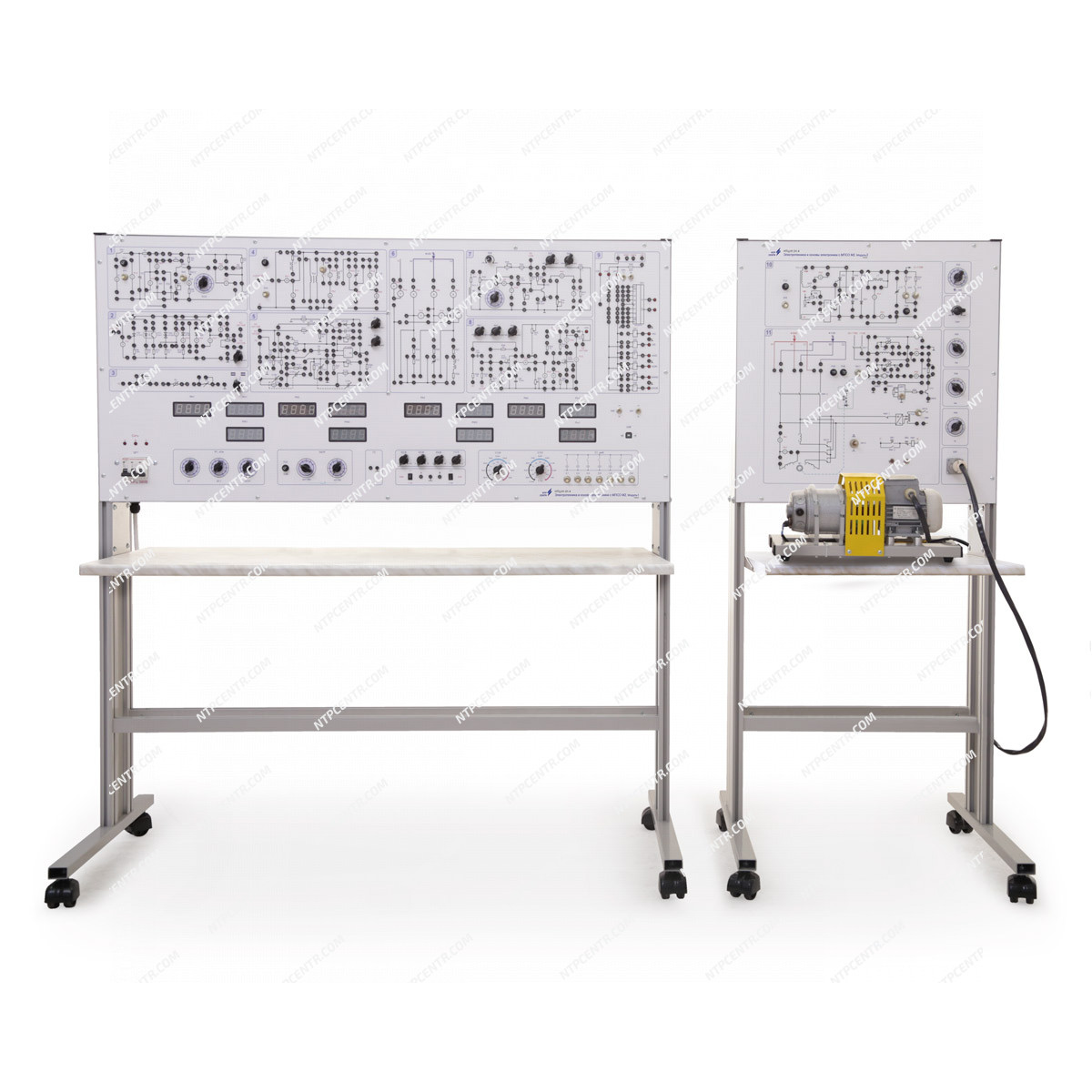
- housings of Module 1 and Module 2, where is mounted a part of electric equipment, electronic cards, front panel and integrated work table top;
- an electric machine unit (twin) containing two electric machines: an asynchronous electric motor with a squirrel-cage rotor and a direct current electric motor of independent/sequential excitation. An optical speed sensor is installed on the machine unit.
The housing of the stand contains:
- power supply unit;
- board of thyristor-controlled rectifier and pulse-width converter;
- adjustable AC voltage source based on autotransformer;
- capacitor stores;
- load resistors;
- digital measuring complex with value displaying;
- card for measuring the rotation speed of electrical machines with indication;
- digital two-channel oscilloscope;
- signal generator.
On the front panels of the stand are shown electrical circuits of the objects under study, which are divided into groups in accordance with the topics of the laboratory work being carried out. The front panels also have switching sockets and equipment, indicators of digital measuring instruments, as well as controls for changing parameters during laboratory work.
The controls and other front panel elements of the Module 1 include:
- mains switch with voltage control in each phase;
- switch block variable resistor;
- laboratory autotransformer switch;
- signal generator output sockets;
- DC EMF regulators;
- jacks for connecting to channels of the built-in digital signal with switches for voltage dividers of the input signal.
- capacitor stores;
- indication of a digital measuring complex.
Measurements are performed using a digital measurement complex built into the stand. The output signals of the complex are transmitted to the inputs of a USB oscilloscope, which connects to a personal computer via a USB interface.
The measurement complex consists of four galvanically isolated multi-channel ADCs, a microprocessor-based measurement system module that provides multi-channel measurements in all three phases with the display of measured values of current, voltage, and power on digital indicators. The measurement complex is capable of measuring both direct and alternating current.
The controls and other front panel elements of the Module 2 include:
- setpoints for the control system of the controlled rectifier;
- switches for adjustable rheostats of the armature and excitation circuits of the DC motor.
- master for PWC;
- connector for connecting a twin of an electromagnetic unit.
The laboratory stand is supplied with:
- software for automatically establishing communication with the stand when it is connected to a PC, visual displaying of measurement results on the PC screen in real time mode, grouping the displayed data depending on the laboratory work performed, automating the process of registering the received data with adding them into a table, copying or saving data for further processing;
- USB Oscilloscope Software;
- a set of teaching materials and technical documentation intended for the teaching staff.