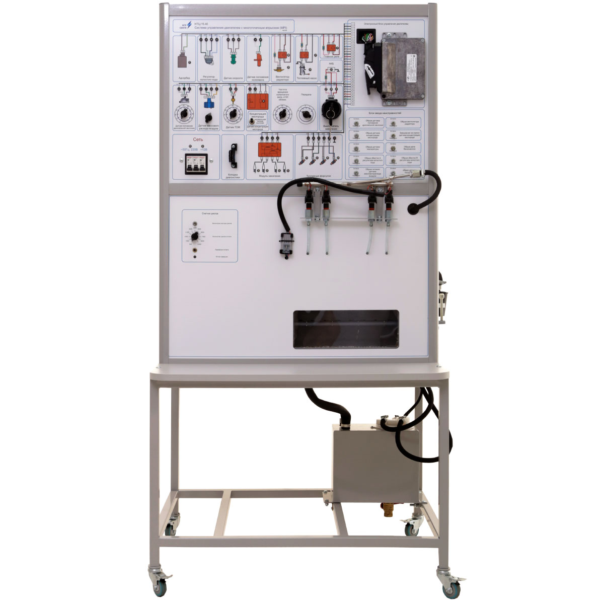
The stand provides clearness during the investigation of operation of injection engine control system. Also it can be used for diagnosis and determination of operating characteristics of injection engine control system elements.
Structurally the training system consists of a metal frame with the following equipment installed: internal combustion engine, a fuel tank with a fuel pump and filter, an aluminum frame with a working panel.
In the upper parts of the front panel there are sensors (speed, crankshaft positions, throttle positions, air mass flow, oxygen concentration, coolant temperature), actuators (adsorber, idle speed regulator, radiator fan, fuel pump, main relay, ignition module, fuel injectors), ignition switch, rear crankshaft speed sensor and diagnostic engine electronic control system, fault input unit. Near the images of the sensors there are test points to take the signals from the sensors, and regulators that allow to change these signals. Control points and status indicators of these devices are also placed next to the images of actuators.
In the lower part of the front panel there is a fuel rail with nozzles, an injected fuel flow meter with the ability to measure fuel consumption individually for each nozzle, a cycle counter, which allows you to turn off the fuel supply through a specified number of engine cycles.
As a working fluid of the injection system, instead of gasoline, injector test fluid is used, which is supplied from a tank with an electric fuel pump through a fine filter in a BOSCH fuel rail with solenoid nozzles.
In the stand there is the possibility of electronic diagnostics of operation parameters and faults using the SCANMATIC diagnostic scanner and its analogues, as well as the forced introduction of faults with their subsequent diagnostics and localization.
Fault introduction unit allows the user to introduce the following malfunctions:
- crankshaft position sensor (CPS) interruption;
- throttle position sensor (TPS) interruption;
- oxygen concentration sensor (lambda probe) interruption and short circuit to frame;
- radiator fan interruption;
- idling regulator (IR) winding interruption;
- coolant temperature sensor (CTS) interruption;
- air mass flow rate sensor (AMFRS) interruption;
- gasoline pump relay interruption.
The training system is accompanied with:
- a set of teaching materials and technical documentation intended for the teaching staff;
- software.