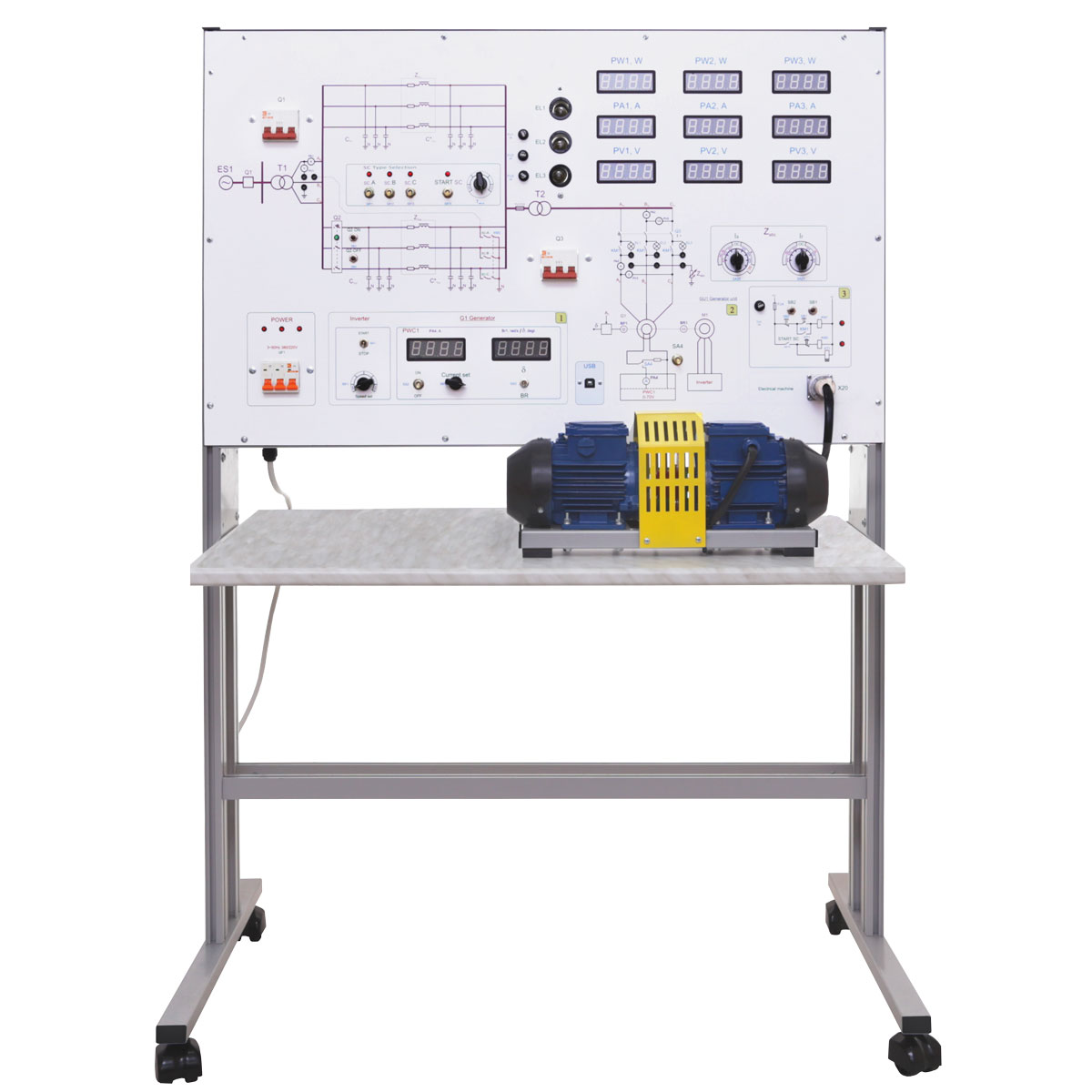
Structurally, the training system consists of two parts:
- case with some of electric equipment installed, electronic boards, the front panel and the integrated tabletop;
- electric machine, consisting of one synchronous generator, one asynchronous electric drive with square-cage rotor and optical speed sensor.
The training system is supplied with electric machine, based on 90W electric drives.
The following equipment is located inside the case:
- Frequency converter, which is used to form three-phase circuit alternating current, controlled by frequency and supply voltage of the gon asynchronous electric motor with a short-cirtrotor.
- DC PSU, which is used for power supply of the circuit of synchronous generator rotor.
- Measuring module, based on digital measuring complex built-in the training system, which could be connected to a PC via USB bus (it also includes a USB-oscilloscope).
- Relay-contactor control, which allows to:
- connect the generator to parallel work with 3~50 Hz 380/220 V circuit;
- connect the branches of double circuit power lines selectively between power mains and synchronous generator;
- change capacity value of 3-phase powerline branches;
- set the type of short-circuit, adjust the creation time of short-circuit between 1-10 sec.
- Light bulbs for synchronization of three-phase generator with circuit.
- Resistors and chokes, modeling active and inductive power line resistances.
- Resistors, capacitors, chokes, modeling active and reactive load of synchronous generator.
The front panel includes:
- switch sockets;
- digital instruments’ indicators;
- switching devices;
- control elements for adjusting the properties of the investigated elements during experiment.
Control elements:
- setting potentiometer of the excitation current of synchronous generator;
- setting potentiometer of frequency converter, allowing to smoothly change the value of the output frequency and output voltage supply of gon asynchronous motor with square-cage rotorwafer switches;
- setting active and reactive load parameters of synchronous generator;
- relay subsystem control elements.
To perform the experiments it’s necessary to assemble the circuit using unified jumpers, which allow to make it without loosing its visibility.
The training system is supplied with:
- a software to test and pass students before the experiment. Both theoretical knowledge and knowledge of the contents of the laboratory work are checked. As a result of testing the student receives the mark;
- a set of teaching materials and technical documentation intended for the teaching staff.