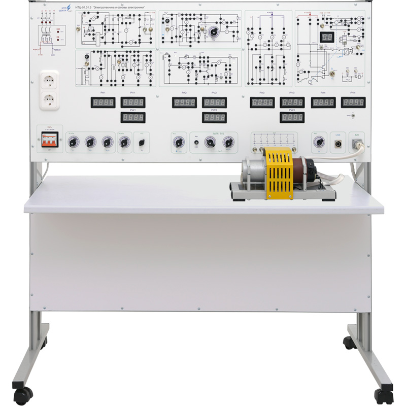
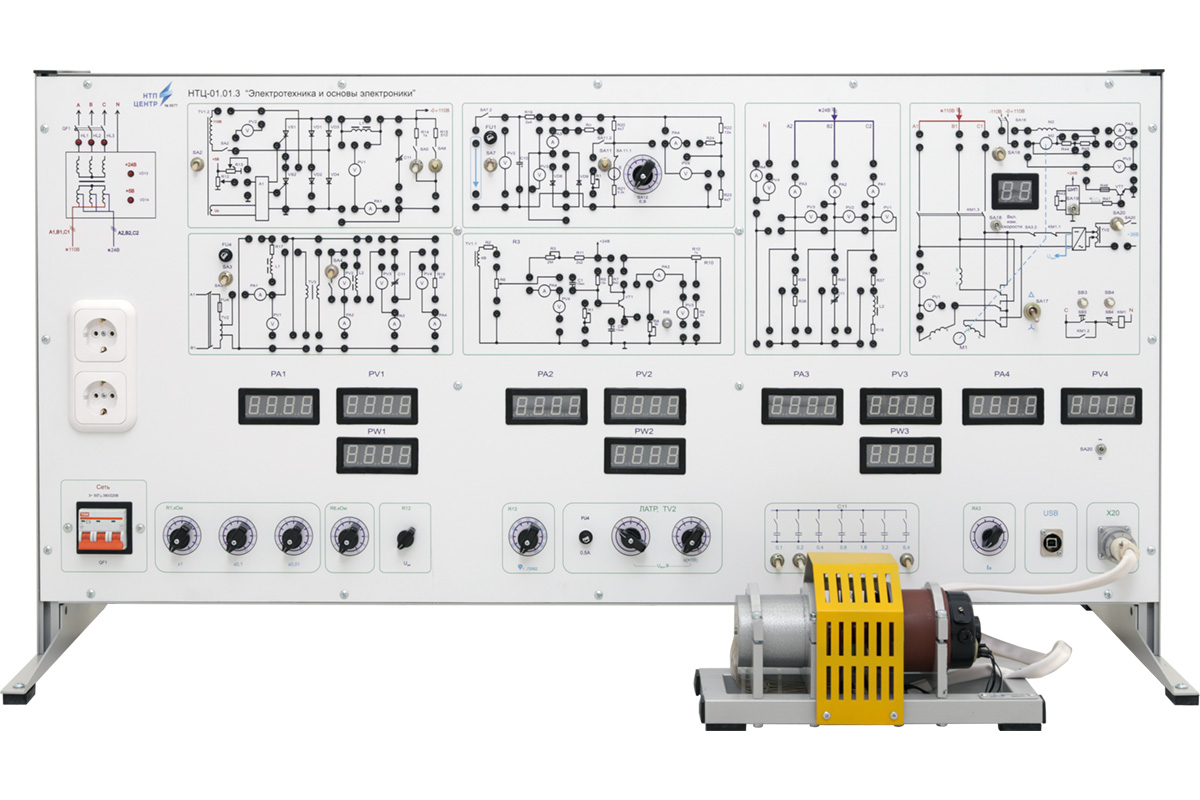
NTC-01.01.3 “Electrical engineering and basic electronics M1”
Br0.00
The educational laboratory stand is designed for studying electrical engineering and the fundamentals of electronics in higher, secondary specialized, and vocational-technical educational institutions. During laboratory sessions, students examine electrical circuits and devices, including methods for measuring resistor resistances, exploring ways of connecting resistors to determine their total resistance, and analyzing voltage and power losses in power transmission lines. An important part of the coursework involves studying the characteristics of linear direct current circuits, as well as the impact of air gaps and parameters of alternating current circuits on their operation. Special emphasis is placed on the operation of three-phase systems and transformers, as well as the analysis of circuits with non-sinusoidal currents and voltages. The study includes electric motors and drive systems, as well as semiconductor devices such as diodes and transistors. In the area of filters and resonant circuits, methods for signal smoothing and extracting specific frequency components are considered. Additionally, the research covers amplifiers and oscillators for generating stable signals. A key component involves working with digital electronics—including logic gates, flip-flops, counters, and other digital circuits used for automation and data processing.
*For additional information, you can contact us via the phone numbers or email provided on the website.
 Русский


