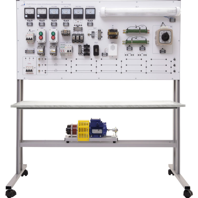
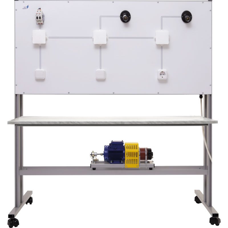
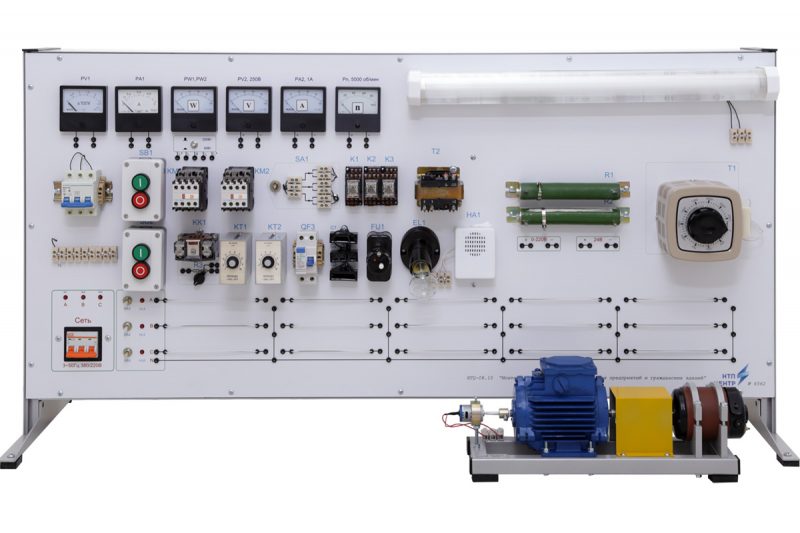
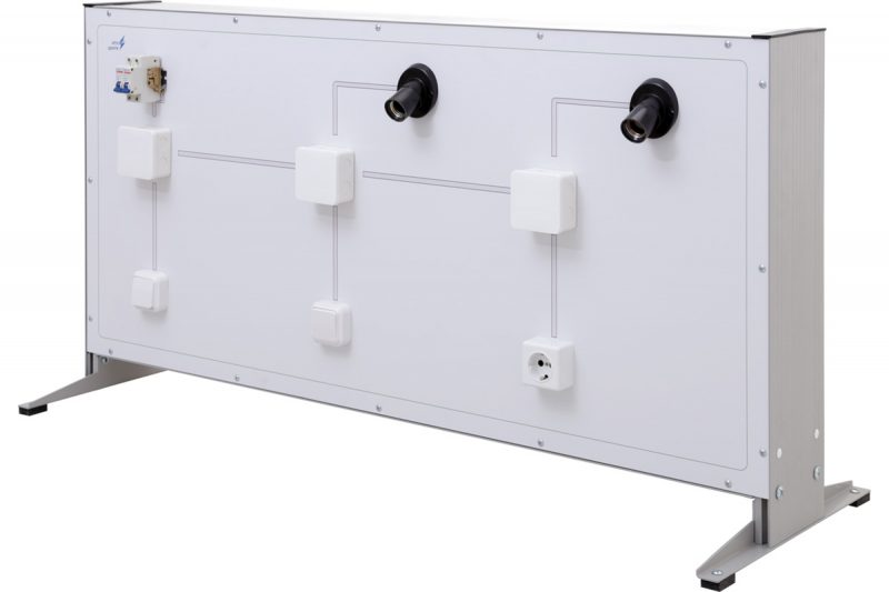
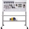
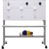
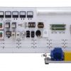
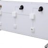
NTC-08.15 “Installation and maintenance of electric power networks for industrial enterprises and households”
Br0.00
The educational laboratory stand for the operation of electrical equipment of industrial and civil facilities is designed for conducting laboratory work on studying specific types of electrical equipment used in enterprises and civil buildings. The stand enables testing and research of electrical engineering devices and systems, including electric motors, transformers, cable lines, and lighting systems. It also allows for studying diagnostic methods, protection techniques, and troubleshooting in automated electric drives and power grids.
*For additional information, you can contact us via the phone numbers or email provided on the website.
 Русский
