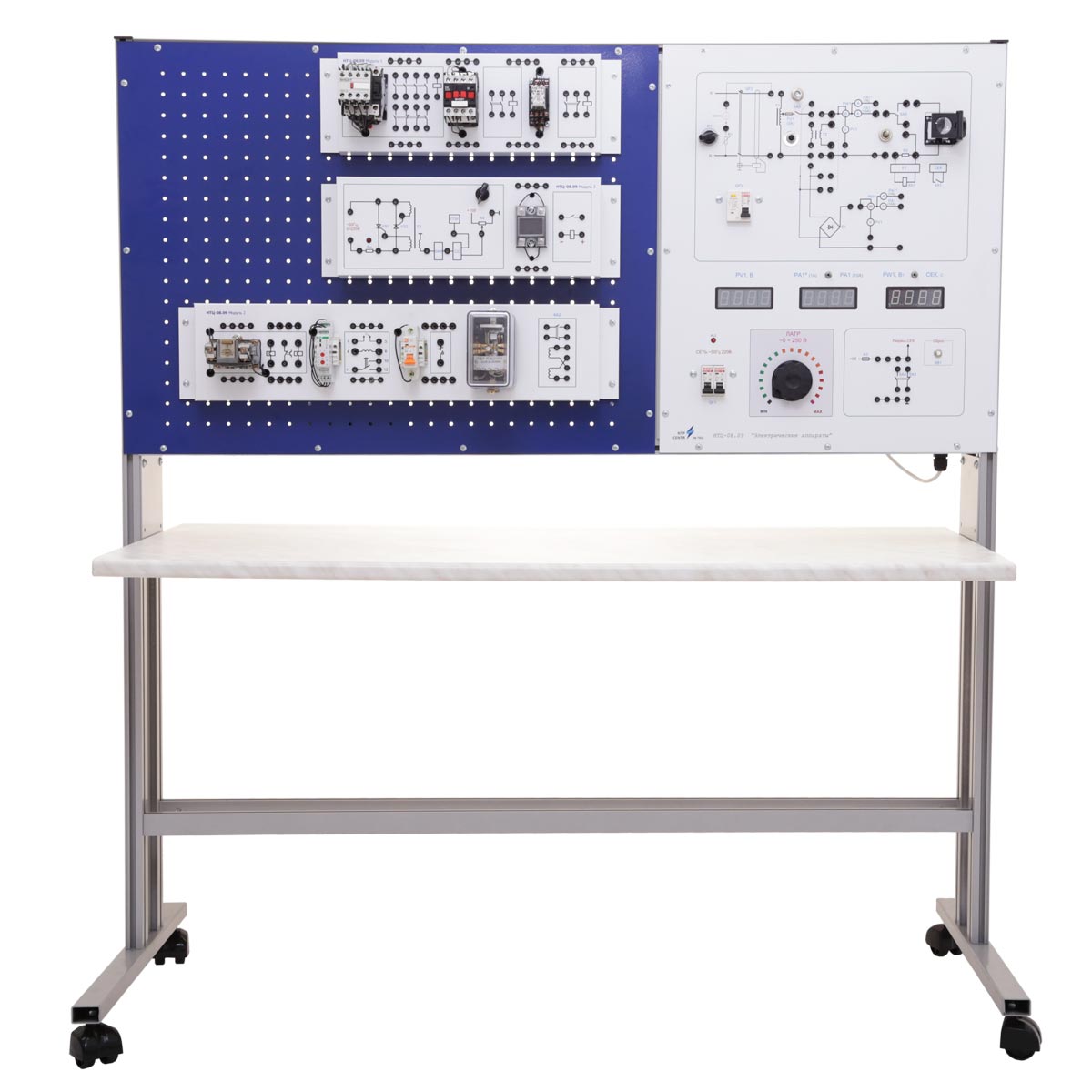
Electric schematics of power supply sources with measurement equipment are displayed on the front panel. The panel includes switch sockets, digital equipment board, stopwatch indicator, switch gear apparatus, adjustment knob of LATR output voltage and receptacle for fuses links installation with a zoom lens, fixed above it. The lens is used for convenience of detailed observation of the burning process of fuse link.
Plug-in modules are located on the perforated mounting panel:
- Module with relay-contactor equipment:
- magnetic actuator of the first value;
- magnetic actuator of the second value;
- intermediate relay .
- Module with protective equipment:
- electric current relay;
- thermal relay;
- automatic breaker;
- maximum current relay.
- Module with electric equipment:
- thyristor voltage regulator with test sockets of control signals and switch sockets of power circuit;
- solid-state relay.
The case consists of:
- power supply unit +5 V (1 А current);
- stopwatch circuit board with measuring range 0,01 – 99,99 sec;
- circuit board of digital measuring equipment with current relay;
- reducing transformer single-phase dry-type multipurpose transformer OSM 1-0,1 220/42 V;
- permanent wire, load resistors PVR-50 22 Ohm;
- LATR autotransformer, 0,4 kW;
- rectifier of LATR regulated voltage;
- power supply transformer single-phase dry-type multipurpose transformer OSM1-0,1.
The controls:
- breaker of laboratory LATR;
- potentiometer to regulate leakage current of RCCB;
- operating modes switches of digital measuring equipment;
- stopwatch reset button.
To conduct laboratory experiments it’s necessary to assemble electric schematic of investigated object, using jumpers.
The training system is supplied with:
- a software to test and pass students before the experiment. Both theoretical knowledge and knowledge of the contents of the laboratory work are checked. As a result of testing the student receives the mark;
- a set of teaching materials and technical documentation intended for the teaching staff.