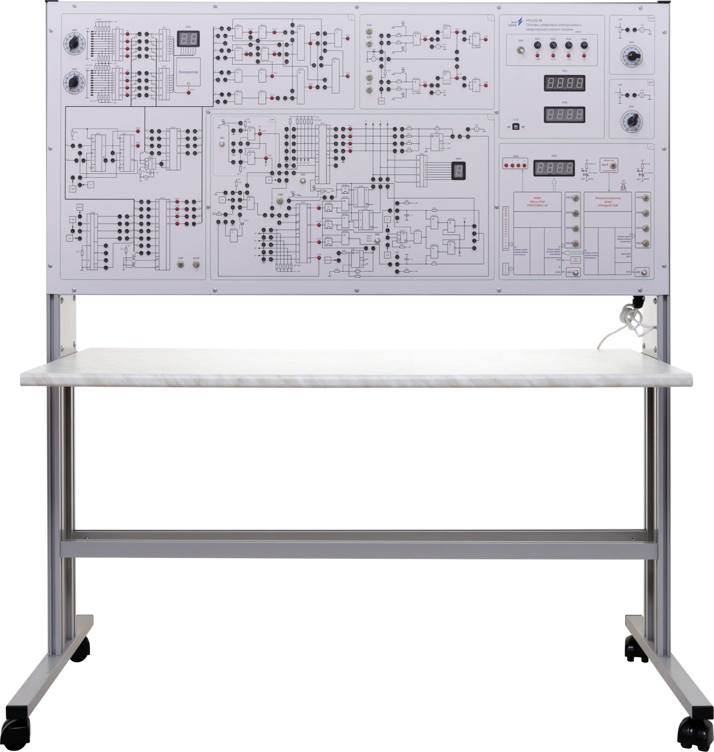
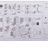
Has two h/w versions: full size bench top version and table version.
The following equipment is installed inside the case:
- the plate of power unit ± 15 V (0,5 А current), + 5 V (0,5 А current);
- the plate of decoders, indication drivers;
- the plate of adder discrete logic, comparator;
- the plate of coder, integrated analog-to-digital converter, register with D-triggers;
- The plate of levels converters (TTL→ CMOS, CMOS→ TTL), counter with JK-triggers with 3/4 division ratio ;
- the plate of shift register, counter with 10 division ratio;
- the plate of analog-to-digital converter in discrete version;
- the plate of microcontroller and programmable logic;’
- digital voltmeters.
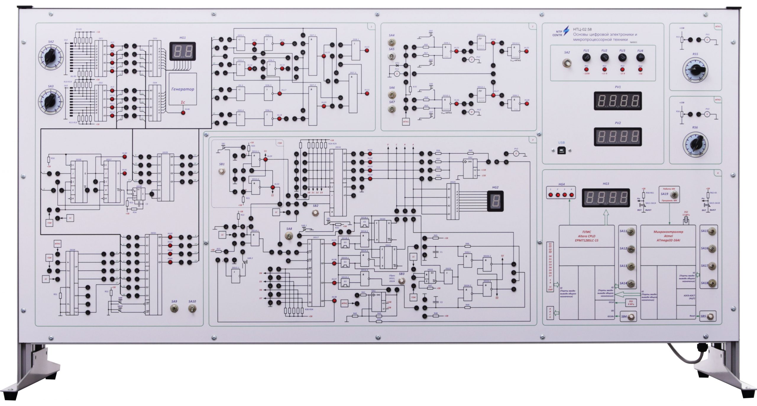
Electric schemes of investigated objects are displayed on the front panel of the training system. All schemes, displayed on the panel, are divided into groups, according to the theme of investigated experiments. The switch sockets, switch gear apparatus and the control unit, allowing to change the characteristics of the elements during laboratory experiments, are located on the front panel of the training system.
Functionally, the front panel is divided on the units:
- Coder/decoder unit. Allows visually investigate the coder and decoder operating. To set coder input signal a multiposition switch is used. The condition of coders outputs is the input signal for conversion of the binary code in the code of the seven-segment indicator and it’s controlled by LEDs.
- Discrete logic block. Allows to collect the half-adder, adder, multiplexer, demultiplexer and comporator schematics. The input data for the schematics are measured from integral coders. The condition of mid-term and input signals is controlled by LEDs.
- The unit of TTL and CMOS basic elements. Allows to investigate the basic element NOT-AND in TTL and CMOS bases, level converter for TTL and CMOS schematics ratio. During the investigation, voltage is regulated at the input of the elements (from 0 to Upow microchip). It’s possible to change power voltage for CMOS (Upow = 0 ÷ 15 V). Power and input signals voltage is changed, using potentiometer. The control is made by two digital voltmeters.
- The elements unit of integrated form. Allows to investigate the counter, based on JK-triggers with counting ratio 3,4, integral register, based on D-triggers, digital-to-analog converter of integrated form.
- The unit of digital-analogue and analogue-digital discrete converter. Allows to investigate classical schematics of digital-analogue and analogue-digital (successive approximation) converter. Shifting register, reversible counter, RS-, synchronous RS-, counter T-triggers are investigated in the same unit.
- Microcontroller and programmable logic unit.
- Voltmeters unit.
- Fuses unit.
To conduct laboratory experiment it’s necessary to collect the scheme of the investigated object, using the unified jumpers, allowing to show the scheme in visual form.
The measurements are made, using digital measurement equipment (voltmeters).
The training system is supplied with:
- a software to operate with PLD and microcontroller.
- a set of teaching materials and technical documentation intended for the teaching staff.