Besides all options of “Electronics”, the bench contains an additional module of microcontroller and programmable logic device (PLD), a digital multichannel oscilloscope; the list of labs based on operational amplifier (bandpass filter circuits) is expanded.
Structurally the bench consists of a body, in which electrical equipment, electronic boards, the front panel and an integrated desktop are installed.
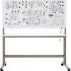
Has two h/w versions: full size bench top version and table version.
The following equipment is located inside:
- power supply unit +12 V 0,5 А, -12 V 0,5 А, +5 V 0,5 А;
- operational amplifier board;
- transistor amplifier board;
- controlled thyristor rectifier board;
- generator board;
- logical element board;
- programmable logic and microcontroller board.
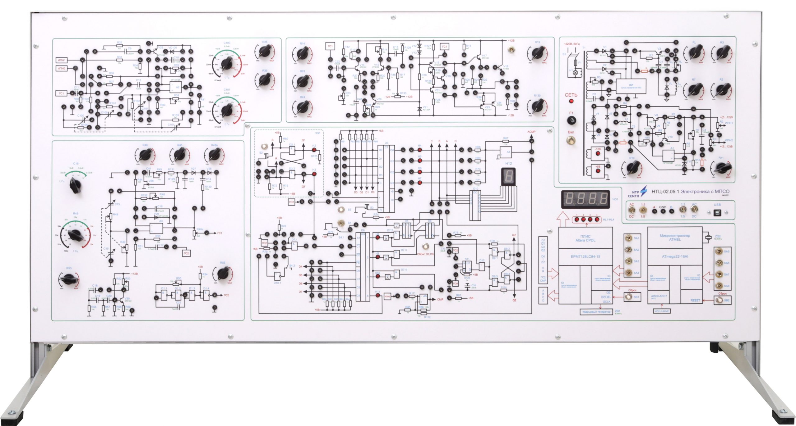
On the front panel the wiring diagrams of studied objects are depicted. All the circuits depicted on the panel are divided into groups in accordance with the theme of work done. There are also switching jacks, digital indicators, switchgear, and controls allowing students to change the parameters of the elements during the laboratory work.
Functionally the front panel is divided into 6 units:
- Power supply unit. Within this unit the first three labs can be conducted. The unit enables the study of potentiometric stabilizer, the influence of various passive RC- and LC-filters and active on bipolar transistor on the power supply output voltage, thyristor rectifier.
- Unit for the study of circuits on bipolar transistors. The unit allows students to investigate the classical types of amplifiers: single stage (common emitter), differential, power amplifier and emitter follower (common collector). All circuits are parts of the power amplifier circuit. The input signal is the output signal of RC-oscillator to the operational amplifier with Wien bridge. The supply voltage can be stabilized 12V and adjustable in the range 0 ÷ 16 V.
- Unit for the study of circuits on the basis of operational amplifier. The unit allows students to investigate the standard amplification circuit (inverting and non-inverting amplifier), repeater, summation, differentiation, integration, comparison (comparator), Schmitt trigger. The input signals can be: a constant signal from a controlled voltage source or a signal from RC-oscillator to operational amplifier.
- Unit for the study of signal generators. The unit allows students to investigate: RC-generator on bipolar transistor, RC-oscillator on operational amplifier with Wien bridge, with and without AGC, multivibrator on operational amplifier, start-stop multivibrator on operational amplifier, RC-oscillator on logic elements.
- Unit for the study of digital technology circuits. The unit allows students to investigate: NOT, NAND, AND gates, synchronous RS-flip-flop, D-flip-flop, JK-flip-flop, T-flip-flop on gates, integral circuits of registers, counters and decoders, DAC with resistor matrix, ADC of successive approximation.
- Unit for the study of microprocessor and programmable logic device (PLD). The unit enables the study of microprocessor (architecture, programming on a PC, work with LED four-digit indication, work as a timer, a collaboration with the PLD, etc.); programmable logic device (PLD) (the study of architecture, programming on a PC, the implementation of any binary logic devices, including all devices used in the bench on discrete elements, work with a microprocessor).
To carry out the work it’s necessary to assemble the circuit of the studied object using standardized jumpers, which allow students to assemble the circuits without loss of clarity.
The laboratory stand is supplied with:
- a software to work with PLD and microcontroller;
- a set of teaching materials and technical documentation intended for the teaching staff.