 Русский


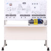


NTC-07.25 “Basic electric drive and converting equipment with MPCS”
Br0.00
The training laboratory system is used to study automated electric drive, power converter equipment, electric drive control systems, automated control systems.
- Description
- Experiments provided
- Technical specifications
- Video
- Scope of delivery
- Additional equipment
- case with installed part of electric equipment, electric circuit boards, countertop of integrated desktop;
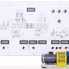
- machine equipment, consisting of one DC electric motor of independent excitation, one asynchronous electric motor with squirrel-cage rotor, optical peed sensor with determination of rotation direction, flywheel for inertia moment creation.
The following equipment is located inside:
- Frequency converter, which is used to form three-phase AC power line of regulated frequency and power voltage of asynchronous electric motor. The converter is based on the microcontroller MB90F562 (Fujitsu), power intelligent module PS11033 (Mitsubishi). The controller is used to count input (voltage, frequency and dynamic braking current setting), output (current, voltage) converter signals, organize data exchange with PC, display the measured values on the front panel of the training system. The power module consists of power circuits of three-phase bridge inverter, based on IGBT-transistors, drivers circuits and protection from short-circuit current, insufficient voltage of drivers supply, fault injection of the control signals. Frequency converter provides the investigation of asynchronous electric motor in all four quadrants of mechanic characteristic, and realizes the dynamic motor braking with regulated current.
- Two pulse-width converters dedicated for power supplying the armature circuit, excitation winding of DC electric motor, active or active-inductive loads. Pulse-width converters are based on the frequency converter. Two its arms are used for reversible PWC, another arm is used as non-reversible PWC to supply DC motor excitation winding. Reversible PWC may operate in symmetrical (alternate diagonal inclusion) or non-symmetrical (diagonal inclusion of one resistors pair) modes.
- Three-phase controlled rectifier is used to investigate the operation in active, inductive and motor load. The rectifier is based on the microcontroller ATMega163 (Atmel) and load thyristors Т122-25. The controlled rectifier has two operating modes: three-phase MCU-controlled, one-phase with analogue system of phase-pulse regulation.
- Measurement module, built on the basis of digital measuring instruments and designed to measure and display the current in the excitation winding of a DC motor, as well as measure voltage and current at the output of the frequency converter.
- Relay-contactor control allows to operate:
- DC electric motor resistor start in three levels in the function of current, electromotive force, time;
- dynamic breaking of DC electric motor;
- DC electric motor braking by back connection;
- dynamic braking of asynchronous electric motor, plugging braking.
Microprocessor unit control of relay-contact control allows to:
- measure current, voltage, DCM speed and save them with the range of 0,1 sec during 10 seconds (total is 100 values) after the start/braking. It allows to construct the graphics of the start/braking without PC;
- produce analogue signals proportional to current and DCM speed; investigate servo driver system, based on the DCM. Speed measurement is carried out on the signals of the pulse position sensor (360 pulses per revolution).
- Analogue regulators are used to investigate:
- closed single-circuit system of current stabilization of DC electric motors;
- closed single-circuit system of speed stabilization of DC electric motor with speed regulator;
- closed double circuit system of speed stabilization of DC electric motor with speed and current regulator.
At the same time, analog controllers have adjustable proportional feedbacks for speed and current.
- Resistors in armature circuit (three levels).
- Resistor of dynamic braking of DC electric motor.
- Power starter of relay subsystem.
- Power discharge resistors in overvoltage on intelligent module.
Electric schematics of investigated objects are shown on the front panel of the training system. All the schematics are divided into the groups according to the theme of conducted laboratory experiments. Switch sockets, digital equipment indicators, switch gear apparatus, controls, allowing to change elements parameters during laboratory experiment, are installed on the panel. The test points of input, intermediate, output signals of power converter equipment are located on the front panel.
The test points:
- input signal of reversible pulse-width converter;
- control signals from the microcontroller to the drivers of intellectual module of all keys of reversible pulse-width converter;
- voltage and current at the output of reversible pulse-width converter;
- current at the output of frequency converter;
- control signals from the microcontroller to the drivers of intellectual module of frequency converter;
- the signals of phase-pulse regulation of thyristor rectifier;
- control signals from the microcontroller to the thyristors;
- current and voltage at the output of thyristor rectifier;
- the signals in closed system of subordinate regulation.
The controls on the front panel:
- setting potentiometer to control the reversible pulse-width converter, tumbler of the converter operating mode (independent/symmetrical);
- setting potentiometer of pulse-width converter to supply the excitation winding of DC electric motor (0 ÷ 500 mА);
- setting potentiometers of the frequency converter, allowing smoothly change the output frequency setting (0 ÷ 89 Hz), output voltage (0 ÷ 220 V), current of dynamic braking of asynchronous electric motor with squirrel-cage rotor (0 ÷ 5 А);
- setting potentiometers of setting signal of closed system, coefficient regulation of inverse current and speed connection;
- setting potentiometer of opening angle of thyristor regulator, tumbler of the operating mode of the regulator (digital three-phase/ single-phase analogue);
- the controls of stopwatch and three starting levels;
- relay subsystem controls.
To conduct the laboratory experiment it’s necessary to assemble the schematic of investigated object, using jumpers, which allow to introduce the schematic in visual form.Laboratory experiment may be conducted in manual mode and in the mode of the dialogue with PC.
The laboratory stand is supplied with:
- methodical and technical documentation set intended for academic staff;
- software which gives opportunity to:
- repeat basic theoretical principles studied in lab;
- check students’ knowledge before conducting laboratory experiments (theoretical questions, correct circuit assembly, knowledge of hardware, step by step control of understanding the selection of the experiment circuit and measuring instruments for the implementation of specific learning objectives);
- carry out laboratory work with displaying the measured values on a computer monitor;
- implement real-time mathematical calculations of measured electrical quantities and their graphic display;
- save the data obtained and work with them when the bench is off;
- export the data obtained (graphs, oscillograms, estimates) to Office programs in order to provide convenience of subsequent reporting.
Experiments provided
- Investigation of static mechanical and electromechanical characteristics of DC motor with separate excitation.
Measurement of the natural and artificial static DC motor characteristics with independent excitation in three quadrants. - Investigation of static mechanical and electromechanical characteristics of asynchronous motor with squirrel-cage rotor.
Measurement of natural and artificial static characteristics of the asynchronous motor with squirrel-cage rotor in three quadrants. - Investigation of analog system of single-phase controlled rectifier of pulse-phase control.
Investigation of the schematic and formation principle of control signals on SPIC of vertical acting. - Investigation of single-phase controlled rectifier.
Investigation of the operation of single-phase controlled rectifier on active, active-inductive loads and back-EMF. - Investigation of three-phase controlled rectifier.
Investigation of the operation of three-phase controlled rectifier on active, active-inductive load and back-EMF. - Investigation of three-phase pulse-width converter.
Investigation of the schematic and operating principle of pulse-width converter on IGBT-transistors. - Investigation of three-phase autonomous inverter.
Investigation of the schematic and operating principle of offline voltage inverter on IGBT-transistors. - Experimental determination of moment of inertia.
Determination of the inertia moment of joined electric motors by the method of coasting. - Investigation of static mechanical characteristics of DC motor with separate excitation in braking modes.
Measurement of static characteristics of the dynamic braking, generator mode, the mode of DC motor back connection with independent excitation. - Investigation of DC motor with separate excitation braking methods.
Investigation of the dynamic braking and back connection of DC motor with independent excitation. - Investigation of DC motor with separate excitation variable-resistance start.
Investigation of rheostat starting in the function of time, EMF, speed and armature current of DC motor with independent excitation. - Investigation of DC motor with separate excitation starting processes.
Investigation of armature voltage and excitation flux influence on the starting process of DC motor with independent excitation. - Investigation of asynchronous motor with squirrel-cage rotor starting processes.
Investigation of frequency and starter frequency influence on the starting process of asynchronous motor with squirrel-cage rotor. - Investigation of asynchronous motor with squirrel-cage rotor braking methods.
Investigation of the dynamic braking and back connection of asynchronous motor with squirrel-cage rotor. - Investigation of static mechanical characteristics of asynchronous motor with squirrel-cage rotor in braking modes.
Measurement of static characteristics of the dynamic braking, generator mode and back connection of asynchronous motor with squirrel-cage rotor. - Investigation of current control loop in system of pulse-width converter-DC motor.
Calculating of regulators and investigation of static characteristics of automated current regulation system in different coefficients of back current connection. - Investigation of speed control loop in system of pulse-width converter-DC motor.
Calculation of the regulators and investigation of static characteristics of automated speed regulation system in different coefficients of back speed connection. - Investigation of slave control in system of pulse-width converter-DC motor.
Investigation of static characteristics of subordinate regulation system in proportional and proportional integral speed regulators. - Investigation of positional control in system of pulse-width converter-DC motor.
Investigation of position control system. Investigation of the formation principle of quadrature signal of the pulse position sensor.
Technical specifications
| Power supply | 3~50 Hz, 220/127 V 3P+PE+N (from step-down 380/220V transformer) |
| Power consumption, kW, max | 0,5 |
| Overall dimensions, max: | |
| width, mm | 1310 |
| height, mm | 1460 |
| depth, mm | 600 |
| Overall dimensions of the machine unit, max: | |
| length, mm | 400 |
| width, mm | 150 |
| height, mm | 180 |
| Weight, kg, max | 85 |
| Overall dimensions of desktop version of the training system, max: | |
| width, mm | 1310 |
| height, mm | 680 |
| depth, mm | 450 |
| Overall dimensions of the machine unit, max: | |
| length, mm | 400 |
| width, mm | 150 |
| height, mm | 180 |
| Weight, kg, max | 50 |
Measurement specifications:
| Number of displayed parameters | 11 pcs. |
| Voltmeters | 2 pcs. |
| Ammeters | 3 pcs. |
| Frequency meter | 1 pc. |
| Speed meter | 1 pc. |
| Converter duty cycles | 2 pcs. |
| Angle of thyristor regulator control | 1 pc. |
| Multifunctional control menu of relay-contact group | 1 pc. |
| Range of measured voltage | from ±0,1 V to ±750 V |
| Range of mesured current | from ±500 mkA to ±10 А |
| Range of measured speed | from ±1 rad/sec to ±314 rad/sed |
| Range of measured frequency | from 0 Hz to 89 Hz |
| Range of mesured time intervals | from 0,1 sec to 9,9 sec |
| Regulation range of the duty cycle of pulse-width converters | from 1 to 99 % |
| Measurement accuracy | 1% |
Technical specifications of the pulse-width converter:
| Rated current | ±3 А |
| DC link voltage | 300 V |
| Converter grequency | 8 kHz |
| Current overload | ±5 А |
Technical specifications of frequency converter:
| Motor power | 400 W |
| Rated current | 3 А |
| Operating range of output voltage | 3~ 220 V |
| Control method | sinusoidal PWM (U/f control, independent) |
| Frequency control range | from 0 to 89 Hz |
| Resolution frequency ability | 1 Hz |
| Overload margin | 150% from nominal output current during 1 minute (integral dependence) |
Video
Scope of delivery
- training laboratory system – 1 pc.;
- accompanying materials in electronic format – 1 pc.;
- passport – 1 pc.;
- jumpers set – 1 pc.;
- AM-BM USB 2.0 cable – 1 pc.